Generic
Soldering Practice SMD-SMT CD4511 Numerical LEDS Board DIY Kit Electronic PCB
Soldering Practice SMD-SMT CD4511 Numerical LEDS Board DIY Kit Electronic PCB
Couldn't load pickup availability
Brand: Generic
Mounting Style: Surface Mount
PCB Type: Double-Sided PCB
Material: FR-4,Plastic,Metal
Country/Region of Manufacture: China
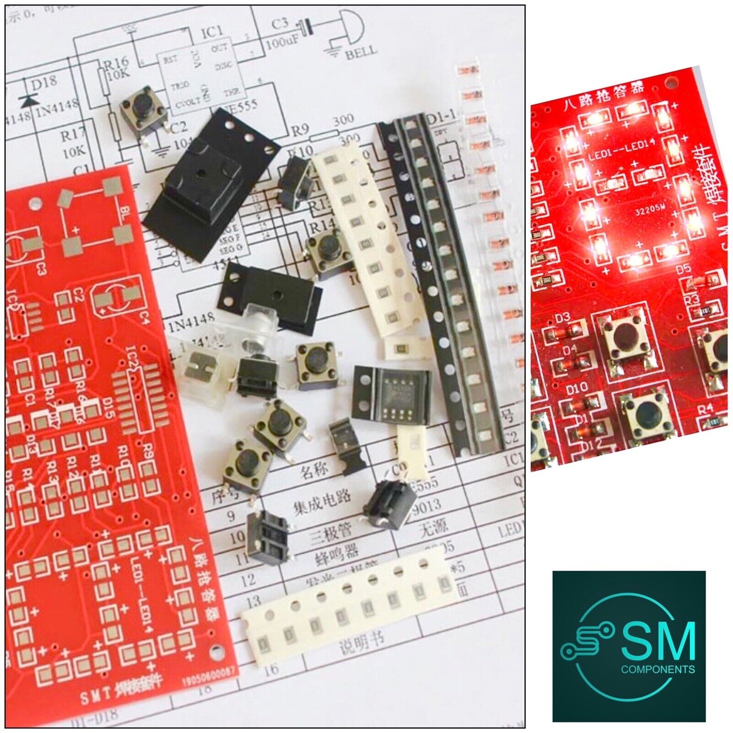
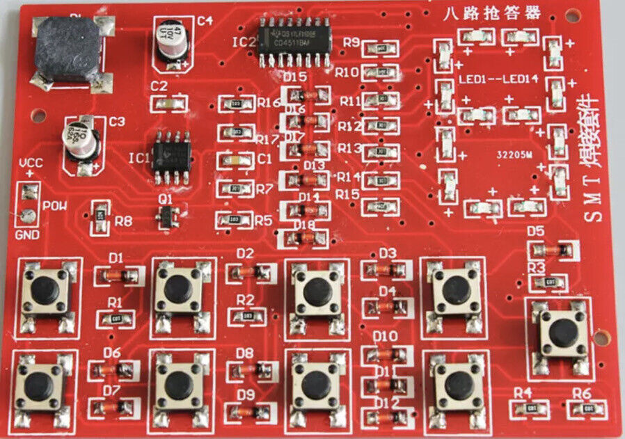
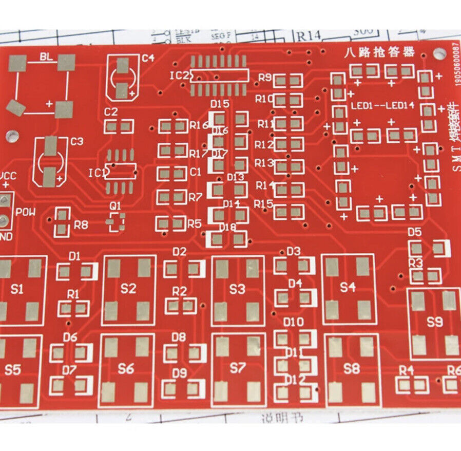
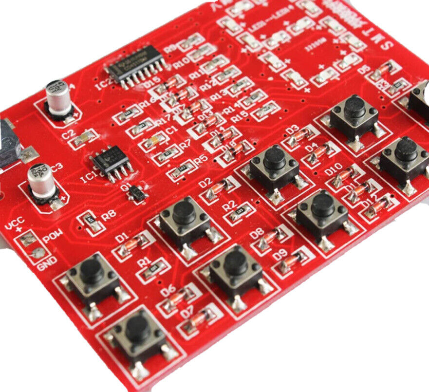
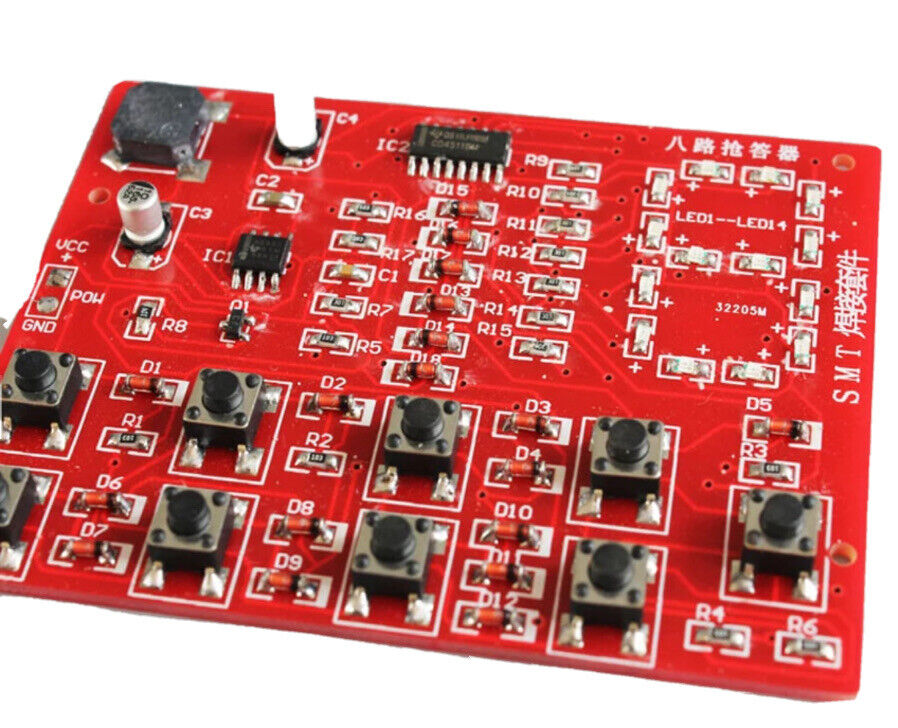
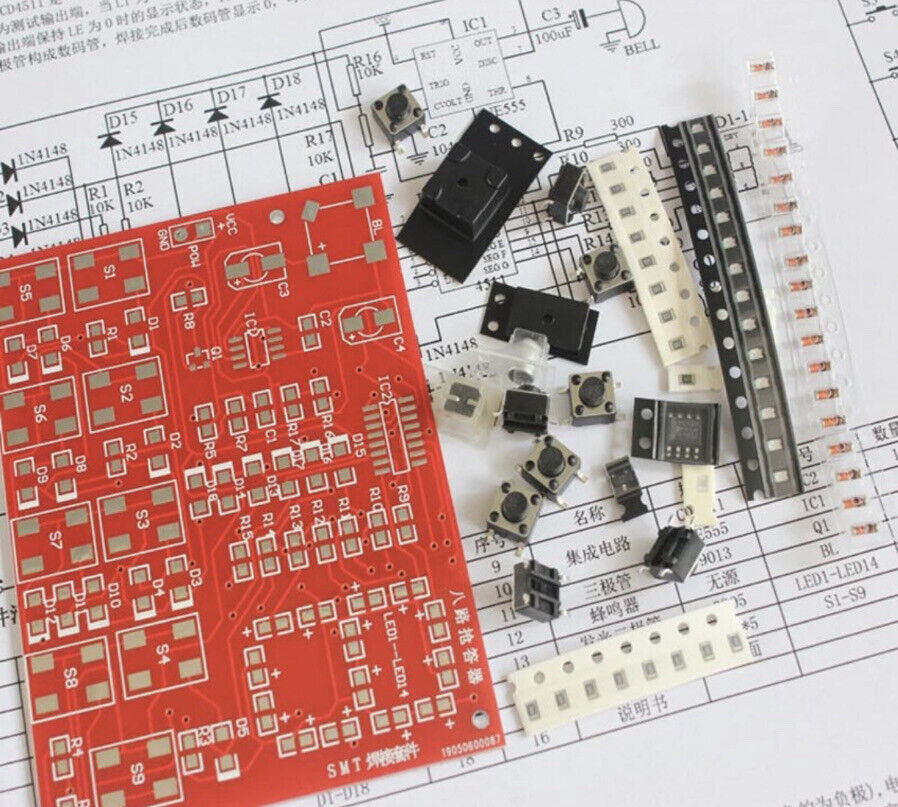
Soldering Practice SMD CD4511 Numerically set out LEDS Board DIY Kit Electronic PCB.
Note:This module is DIY Kit, Not a finished product.
Item is ‘Brand New’ sent with Australia Post Regular Letter, NO TRACKING
Features:
Full Patch Eight-Way Digital Answerer Experiment Kit Patch Answerer Training Kit Electronic Kit
Description:
1. Product description
The full-chip 8-channel digital answerer is a new product specially developed for electronic assembly and debugging skills spot checks. The circuit design adopts the time-base circuit and decoding drive widely used in digital circuits. The circuit components all adopt the current SMD package series. , Is a SMT welding training kit worth learning and circuit analysis.
2. Simple principle
The circuit includes answering, coding, priority, latch, digital display and reset circuits. Eight-way priority answering can be performed at the same time. After the button is pressed, the buzzer will sound and the number of the priority answerer will be displayed (LED). After the answer is successful, press the button again, the display will not change unless the reset button is pressed. After reset, the display is cleared and you can continue to answer. S1-S8 are the answer keys, and S9 is the reset key. CD4511 is an integrated circuit that contains BCD-7 segment latch/decode/drive circuit. Among them, 1, 2, 6, 7 are BCD code input terminals, 9-15 pins are display output terminals, and 3 pins (LT) To test the output terminal, when "LT" is 0, the output is all 1, pin 4 (BI) is the blanking end, when BI is 0, the output is all 0, pin 5 (LE) is the latching enable end, when LE When changing from "0" to "1", the output terminal keeps the display state when LE is 0. Pin 16 is power positive, and pin 8 is power negative. 555 and the peripheral circuit form the responder signal ring circuit. Digital display is composed of light-emitting diodes.
Package include:
1 * Eight-Way Digital Answerer Experiment Kit
Use solder length: 35CM (diameter: 0.6mm)
Sample soldering time: 50-60 minutes
Note:
Please allow 0.5-1cm errors due to manual measurement
Item color displayed in photos may be showing slightly different on your computer monitor since monitors are not calibrated same
*This board is a practice board. It is mainly used for practice welding. There are no specific parameters, so the capacitor and resistance will be shipped
Shipping & Returns
Shipping & Returns
